Learn how to recognize non-physiological (external) artifacts in the electroencephalogram (EEG) and how to prevent them.
Electroencephalography (EEG) is a commonly used method to measure the electrical activity of the brain. During an EEG recording, interference from different unwanted sources can prevent you from measuring the signal of interest. These interferences can be categorized in two types: physiological (from within the body) and non-physiological (external). In a previous blog, the most common physiological artifacts were covered. In this blog, the non-physiological artifacts, or external artifacts, will be covered. These artifacts do not originate from inside the body. This blog will describe how to recognize these artifacts on an EEG and discuss how to prevent or remove them.

Types of non-physiological EEG artifacts
The most common non-physiological artifacts are:
- Mains interference,
- Electrode pop,
- Cable movement,
- Bad channel connection.
Which EEG artifacts are caused by mains interference?
One of the most common non-physiological artifacts present in EEG is mains interference. This environmental artifact originates from power leads (220 V / 50 Hz in most European countries, 110 V / 60 Hz in many others) that surround the body and can additionally arise from electromagnetic interference.1
![]()
Figure 1: Mains interference seen toward the right of the EEG.
Mains interference artifacts can be seen on an EEG recording with frequent, monotonous waves at 50 or 60 Hz (Figure 1). In Figure 2, the 50 Hz waveforms per second can be clearly seen.

Figure 2: Closer (zoomed in) look showing frequent, monotonous waves of mains interference on EEG.
In post-processing, this artifact can be suppressed with a notch filter.1 To prevent this artifact, TMSi uses active shielding to minimize this mains interference. With active shielding, each individual lead is shielded by the signal itself by means of a small coaxial cable. The mains interference cannot reach the core of the lead, meaning that there is no capacitive coupling of the mains on the cable. Read more about mains interference here.
Which EEG artifacts are caused by an electrode pop?
An electrode pop can occur when the electrode becomes loose or if it is bumped by something in the environment.2 Most often, an electrode pop is caused by a loose electrode. On an EEG recording, an electrode pop is marked by a sudden shift to the new offset (DC) value or the signal suddenly goes out of range. This can be seen at electrode C4 in Figure 3.
To prevent this artifact, all electrodes should be fixed tightly to the scalp prior to beginning a measurement. To manage this problem during a measurement, check the electrode causing the artifact and fix it back onto the scalp.
![]()
Figure 3: Electrode Pop at electrode C4 on EEG.
Which EEG artifacts are caused by cable movement?
Cable movement can also cause artifacts in non-wireless EEG setups. This is due to the triboelectric noise that is caused by the friction of the cable’s components or the motion of the conductor within the magnetic field.3 On an EEG recording, this artifact will show up as sudden, high amplitude changes in the time domain. To avoid the first cause of this artifact, special low noise components that reduce the friction within the cable can be used.3 The second cause of these artifacts can be solved by using active shielding, as the capacitive coupling is eliminated and the cable can move around freely in space. Read more about movement artifacts here.
Which EEG artifacts are caused by a bad channel connection?
If a channel (or reference channel) is placed incorrectly or has poor connection with the skin, this can result in an artifact. The artifact will present on an EEG recording as non-EEG signals throughout the entire recording.
Please take care than when average referencing is used, one bad channel will influence all channels in the recording. Alternatively, when using a common reference, artifacts in one bad channel will not affect all other channels, but a good connection of the reference channel becomes even more important.
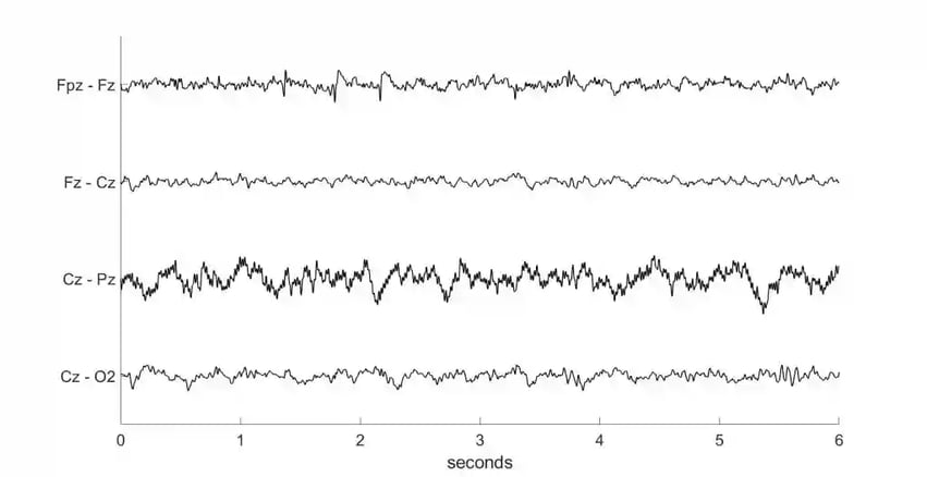
Figure 4: Bad channel connection (Pz) on EEG.
A bad channel connection (Pz) with a slight 50 Hz interference artifact can be seen in Figure 4. To prevent this artifact, make sure your reference electrode is placed correctly before starting a measurement. Also, if possible, check your electrode impedances before a measurement to identify a channel with a poor connection. At TMSi, we provide an amplifier with continue impedance measurements, allowing you to check the channel connections live during measurement.
Conclusion
There are many artifacts that can show up on EEG recordings. The most common non-physiological artifacts are: mains interference, electrode pop, cable movement, and a bad channel connection. To properly deal with artifacts, it is important to recognize the appearance of common artifacts and be able to trace them back to their origins in order to prevent, mediate, or filter them out.
At TMSi, we provide high-quality equipment to considerably reduce artifacts in your research. In our software, you can view channel impedances to ensure electrodes are correctly placed on the scalp before beginning a measurement. Furthermore, we provide cables with active shielding to minimize mains interference and movement artifacts in your research during the measurement. If you would like to learn more about this and our technology, click here.

References
- Urigüen JA, Garcia-Zapirain B. EEG artifact removal-state-of-the-art and guidelines. J Neural Eng. 2015;12(3):031001. doi:10.1088/1741-2560/12/3/031001.
- Valentine D. Artifacts. Learning EEG. https://www.learningeeg.com/artifacts. Accessed October 5, 2022.
- Symeonidou ER, Nordin AD, Hairston WD, Ferris DP. Effects of Cable Sway, Electrode Surface Area, and Electrode Mass on Electroencephalography Signal Quality during Motion. Sensors (Basel). 2018;18(4):1073. Published 2018 Apr 3. doi:10.3390/s18041073.