Explaining the International 10-20 System for EEG
What is the 10-20 System?
The 10-20 system of the international federation is an internationally recognized method that uses anatomical landmarks to standardize the placement of electroencephalography (EEG) electrodes.1 The system is based on the relationship between electrode location and the underlying area of the cerebral cortex whilst ensuring that all brain regions are covered.
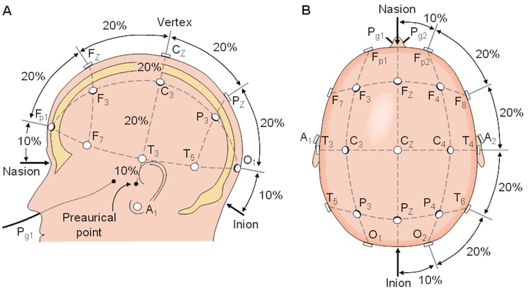
Figure 1: The 10-20 system with front-back (nasion to inion) 10% and 20% electrode distances (picture source).

How does the 10-20 System work?
The 10-20 system was first presented at the 1957 Brussels IV International EEG Congress by Herbert Jasper, to standardize the method of EEG placement.2 The numbers “10” and “20” refer to the distances between adjacent electrodes, which are either 10% or 20% of the total distance (front-back or right-left) of the skull. The total distance is based on the anatomical locations on the scalp: nasion and inion (front-back direction) and the two preauricular points (right-left direction) as seen in Figure 1. Using these anatomical landmarks, the placement of the electrodes can be determined along with these directions with the pre-specified proportions: 10% is used from the anatomical landmarks and the first electrode in that direction, and 20% is used between the other electrodes. For example, the Fp1 is placed at 10% of the total distance from the nasion, and Fz is placed at 20% of the total distance from Fp1.
EEG Electrode Placement
Electrodes have a name that traditionally consists of one or more letters and a number. An example of the 10-20 system layout with electrode labeling is shown in Figure 2.
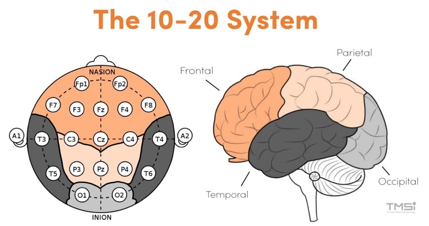
Figure 2: The electrode layout of the 10-20 system (left) and corresponding brain regions (right) (pictures adapted from photo and photo).
What do the letters in the 10-20 System represent?
The letter of the electrode stands for the general brain region that the electrode covers. From front to back, the electrode letter labeling is as follows: Fp (pre-frontal or frontal pole), F (frontal), C (central line of the brain), T (temporal), P (parietal), and O (occipital). Electrodes lying between these lines combine multiple letters, ordered from front to back. This applies to the higher-density systems, which is further explained in the next section. In addition, the letters M and A are sometimes used to refer to the mastoids or earlobes respectively. Typically, these locations are included to serve as a (offline) reference for signal analysis.
What do the numbers in the 10-20 System represent?
The number of the electrode gives information about the distance from the electrode to the midline of the brain. At the midline, the electrodes are labeled with a ‘z’ to represent zero. The electrode numbers increase as you move away from the midline. Odd numbers represent electrodes on the left hemisphere and even numbers represent electrodes on the right hemisphere.
Why is electrode placement in the 10-20 System important?
Repetitive results can only be obtained when the headcap is placed correctly, i.e., if the electrodes cover the desired location on the scalp. Therefore, it is important to choose the right size headcap and to check if Cz is in the middle between the nasion and inion and the two preauricular points.
What are the extensions to the 10-20 system?
In addition to the 10-20 system, there are other higher resolution systems such as the 10-10 system (10% system)3 and the 10-5 system (5% system).4 These systems are an extension of the original 10-20 system, and use additional electrodes between the existing system, resulting in a higher density measurement. An example of the 10-10 system can be seen in Figure 3.
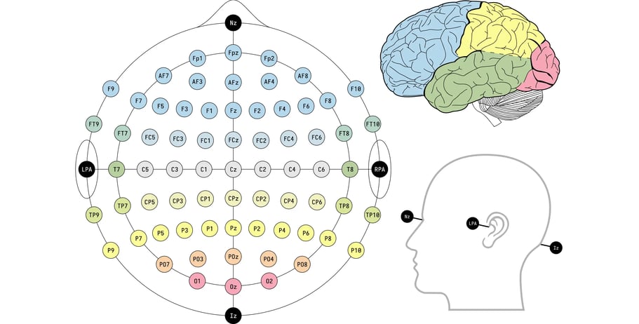
Figure 3: EEG layout with 10-10 system (picture source)
Conclusion
In summary, the 10-20 system allows for equal inter-electrode spacing and the electrode placements to be proportional to skull shape and size. Knowledge of this system and the method behind it allows for a consistent and replicable method of recording EEG. This system is used in various applications, including sleep studies, EEG exams, and other EEG research and clinical studies.
TMSi provides EEG headcaps based on the 10-20 system, as well as the 10-10 and 10-5 system, to match the needs of your research. The available headcaps contain extensions (for 10-20) or subsets (for 10-10 and 10-5) to the systems, to create 24-, 32-, 64-, and 128-channel setups.

References
1. Webster J, Nimunkar A, Clark J. Medical instrumentation. 4th ed. 2010.
2. Klem GH, Lüders HO, Jasper HH, Elger C. The ten-twenty electrode system of the International Federation. The International Federation of Clinical Neurophysiology. Electroencephalogr Clin Neurophysiol Suppl. 1999;52:3-6.
3. Nuwer MR, Comi G, Emerson R, et al. IFCN standards for digital recording of clinical EEG. International Federation of Clinical Neurophysiology. Electroencephalogr Clin Neurophysiol. 1998;106(3):259-261. doi:10.1016/s0013-4694(97)00106-5
4. Oostenveld R, Praamstra P. The five percent electrode system for high-resolution EEG and ERP measurements. Clin Neurophysiol. 2001;112(4):713-719. doi:10.1016/s1388-2457(00)00527-7